N I N E Q U A D R A T BY:IIEN SOLIHIN

Tutorial Vector

  • Ninequadrat
  • Labels:
  • How to Draw Vector in Flash

    This tutorial is continued from the previous tutorial "How to create Blogger logo in Adobe Flash CS3". To be understand the following this tutorial you must read tutorial before about Drawing Techniques in Flash [read the tutorial before this tutorial].  This is tutorial is logical how to simply and easily make photo vector in Flash 5.

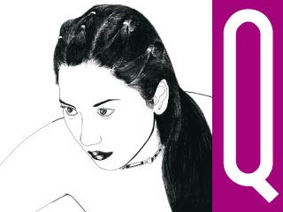
    Result vector from Flash 5
    Not inferior to professional programs are complex vector makers such as Adobe Illustrator, Flash program can also be counted on to make the vector. Her special FLASH 5, with his tools that are still simple, its a user interface view and fast supported use of layering quickly. After the test make vector in Flash 5 is so quckly and easily using this program.

    The Techniques to Make Vector in Flash 5
       1. Understanding Drag Mouse movement on the Line Tool and Cursor changed
       2. Covering every angle lines with perfect to close angle (Close Line to Curve)
       3. Patience in drawing one by one line by line to the results of a detailed result

    ..Hopefully helpful ..
    1. Use Line Tool to create vector line
    2. Photo layer to be make vector
    3. Outline Head Layer is first layer make vector. Create this layer first because head is a difficult piece of body. Create detail of face line will be perfect better his face
    4. Outline Body Layer, create this layer after finished Outline Head Layer to be vector
    The Logic Layering to Make Photo Vector in Flash
    - Outline Head Layer
    - Color Head Layer
    - Outline Body Layer
    - Color Body Layer
    - Photograph
    As principal layering COLOR HEAD layer and COLOR BODY layer is Copy Frame OUTLINE HEAD layer and Copy Frame OUTLINE BODY layer after both layer finished make vectoring and coloring.

    The function from Copy Frame as backup outline layer after draw vector line was finished. So if we will be edited line vector or color vector, event we do not redraw a vector.

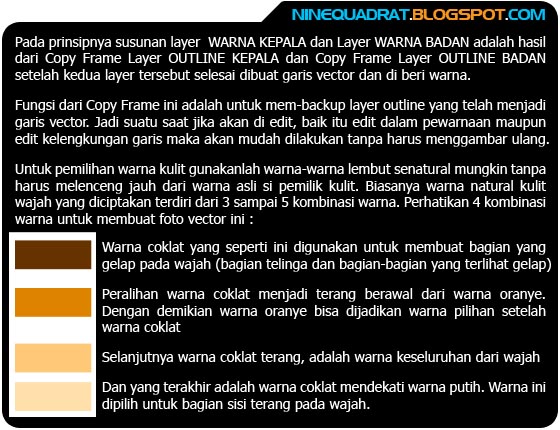
    Best choice for skin color, use soft colors as natural color, same with color skin in photograph. Usually color for skin is consists of 3 to 5 colors combinations. See picture below about 4 color combinations in this vector

    Chose the color of mouth as possibly natural color too for Lips and tongue. Use basic red color from dark red to light red color then chose the color of hair from black to gray color

    Use color for line difference from basic color photograph, like this vector I make this line with red color for User Interface. The choice for Stroke Line use type Hair Line Stroke.

    At the piece of body create detail of body like texture of cloth, folds of cloth, figure of hand etc.

    For maximal coloring can use combination Gradient Color. The Gradient Color will be make a real vector.
    Hopefully Useful!
    Post By: Ninequadrat


    This Article Dedicated to My Students 
    Graphic Design and Animation Class 
    Exelent Program, Daar El Qolam - Banten
    »»  READMORE...

    3 Logo

  • Ninequadrat
  • Labels:
  • H u t c h i s o n W h a m p o a L i m i t e d (H W L) is a leading international corporation committed to innovation and technology with businesses spanning the globe. Its diverse array of holdings range from some of the world's biggest port operators and retailers to property development and infrastructure to the most technologically-advanced and marketing-savvy telecommunications operators. We know this company in Indonesia as Brand 3 Cellular Operator. [Read More]


    Download project 3D MAX animation
    Three logo Indonesia cellular operator


    »»  READMORE...

    Download Ebook Adobe Illustrator CS2

  • Ninequadrat
  • Labels:
  • Creating Vector Content
    Using Live Trace
    A Feature of Adobe Illustrator CS2


    Adobe® Illustrator® C S2 puts industry-standard drawing tools at designers’ fingertips so that they can create graphics for print, video, the web, and mobile devices with ease. And now, with the new Live Trace feature, Illustrator CS2 offers an entirely new way to create vector graphics. Live Trace, a breakthrough tracing tool, lets you convert scanned line art and bitmap images to scalable, editable vector paths and anchor points in just seconds.

    How many times have you roughed out an idea on the back of a paper placemat, only to have to recreate your work from scratch on the computer? How often have you wished you could scan a photograph and convert it directly to a vector graphic as the starting point for an illustration? With Live Trace, you can do both—and more.

    What makes Live Trace “live” is a link that is maintained between the original bitmap image and the traced vector result. You can experiment with tracing options ranging from aesthetic to technical, from color swatches to pixel value thresholds. The traced result updates automatically, even if the original linked bitmap file is modified. Not only is Live Trace live, it’s also intelligent—its choice of the total number and placement
    of anchor points rivals that of the most skilled Illustrator artist.

    This white paper is intended for graphic designers, art directors, freelancers, web designers, print and prepress professionals, and others who are involved in the day-to-day, hands-on creation of graphic materials for print, the web, and mobile devices. It explains how Live Trace works and how you can use it to achieve a high-qua lit y vector foundation on which to build your creative artwork. Read More Download Here
    »»  READMORE...

    Download Font Arabic Collection

  • Ninequadrat
  • Labels:
  • 29 Font Arabic Collection
    Arabic calligraphy, Vintage, Arabic themes


    Archive of freely downloadable fonts. Browse by alphabetical listing, by style, by author or by popularity.


    Size all file : 1.74 MB
    »»  READMORE...

    Index Portfolio 2010

  • Ninequadrat
  • Video Multimedia Presentation
    Make your presentation as an elegant presentation with 3D text,
    visual motion effects logo for your company, event or brand product.
     
     ON YOUTUBE VIDEO

    INDEX PORTFOLIO 2010
    Logo Opening | Home Design Interior and Exterior | Stand Booth Design | CAD Design | Vehicles Model | Stage Design | Logo Company | Footages | Visual Effects Television
    »»  READMORE...

    Tutorial Membuat Background Awan

  • Ninequadrat
  • Labels:
  • How To Create Background Clouds and Background Vortex in Adobe Photoshop


    Step 1
    1. Use Eyedropper Tool
    2. Select in Swatches tab color then use clouds color (CMYK Cyan)
    3. Make sure the foreground color is CMYK cyan and background color is white
    4. Then click menu Filter > Render > Clouds


    The Result Background Clouds
    use menu Filter > Render > Clouds
    Now make this background clouds to be another background (Background Vortex)
    Step 2
    1. Use Eyedropper Tool
    2. Then choose color Darker Cyan Blue
    3. Use Paint Bucket Tool
    4. And change value of Tolerance to 10
    5. Then click in area number 5
    6. Use Filter > Blur > Radial Blur
    Step 3
    1. Change value of Radial Blur like picture below
    For the maximal result, use Radial Blur more then once to make real Vortex Background (3 to 5 more radial blur)
    The Result Background Vortex
    use menu Filter > Blur > Radial Blur
    Hopefully Useful!
    Post By: Ninequadrat

    This Article Dedicated to My Students 
    Graphic Design and Animation Class 
    Exelent Program, Daar El Qolam - Banten
    »»  READMORE...

    Tutorial Desain Panggung

  • Ninequadrat
  • Labels:
  • How To Create Stage Design

    Menanggapi masukan dari rekan-rekan Blogger lain untuk diperbanyak nya Tutorial 3D Max, maka pada kesempatan posting dini hari ini kami tambahkan tutorial cara cepat membuat desain panggung dengan Autodesk 3D Max 2011.
    Pada posting ini kami juga membuka sharing post comments bagi para pengunjung, Mudah-mudahan Tutorial Desain Panggung yang selesai dalam dua minggu ini bisa bermanfaat.

    ..Salam..


    Step 1
    1. Click activated Snap Toggle toolbar
    2. Create Shape with object Type Line
    3. Activated Top Viewport by right click in viewport area
    4. Click full display Top Viewport
    5. Then create a line with 6 corners like the alphabet (a, b, c, d, e, f, g)


    Step 2
    1. After end line at g position, then finish line with close at a position
    2. Appear window dialog "Close spline?" then click Yes

    Step 3
    Still use the Top Viewport and Shapes Line, lets create another 11 objects part of stage use step 1 and also creating Shape Rectangle (2, 3, 4, 8, 9, 10, 11)

    Or you can rename the object properties
    1. Main Trap
    2. Main Back Trap (Rectangle)
    3. Left Side Back Trap (Rectangle)
    4. Right Side Back Trap (Rectangle)
    5. Front Right Side Trap
    6. Front Left Side Trap
    7. Main Front Trap
    8. Back Left Rigging (Rectangle)
    9. Back Right Rigging (Rectangle)
    10. Front Left Rigging (Rectangle)
    11. Back Right Rigging (Rectangle)

    Step 4
    1. Activated Perspective Viewport
    2. Select click Trap number 2
    3. Click Modify
    4. Rename object
    5. Click drop down menu Modifier List
    6. Select Extrude
    7. Then change Amount Parameters Extrude to 16


    Step 5
    1. Do same command Extrude to all Rigging (8, 9, 10, 11) with value of Extrude to :
        Amount = 60
        Segments = 6

    2. By the selected Rectangle Rigging, change all Parameters Rectangle to :
        Length = 5
        Width = 5


    Step 6
    Click activated Smooth + Highlights, then select Edged Faces


    Step 7
    Below is value of Extrude for each all Trap :
    1. Main Trap Amount = 10
    2. Main Back Trap (Rectangle) Amount = 16
    3. Left Side Back Trap (Rectangle) Amount = 16
    4. Right Side Back Trap (Rectangle) Amount = 16
    5. Front Right Side Trap Amount = 13
    6. Front Left Side Trap Amount = 13
    7. Main Front Trap Amount = 7


    Step 8
    1. Click select Rigging
    2. Use Modifier List > then select Lattice
    3. Change value of Struts like the picture 3
    4. Do same again to change value of Joints like Picture 4


    Step 9
    Do same again by using command Modifier List to all each Stage Rigging. For the result like this picture

    Step 10
    1. Click activated Front Viewport > create new Object Shape Rectangle. This part to construct top stage rigging
    2. Then create rectangle like this picture
    3. Activated Top Viewport by right click in viewport area
    4. Change value of Parameters Rectangle to :
        Length = 5.0
        Width = 180
        Corner Radius = 0

    Step 11
    1. Chane Parameters Rectangle to

        Length = 5.0
        Width = 5.0
        Corner Radius = 0

    2. Use Modifier List > then change Parameters to
        Amount = 180.0
        Segments = 14.0

    3. Then use Modifier List again > Lattice with the same Parameters Rigging before


    Step 12
    By using same command Modifier List > Extrude > then Lattice, lets create all Top Stage Rigging, see the picture

    Step 13
    Then activated Front Viewport, then create line Stage Background up to you like the Step 1

    Step 14
    Use also Modifier List > Extrude for all Stage Background then change value of extrude parameters to build a part construction of stage

    Step 15
    The last finishing, create all item construction stage such as Stair of Stage and Big Screen Display at left and right side

    Hopefully Useful!
    Post By: Ninequadrat

    This Article Dedicated to My Students 
    Graphic Design and Animation Class 
    Exelent Program, Daar El Qolam - Banten
    »»  READMORE...
    Related Posts
    (c) Copyright 2010 Ninequadrat . Blogger template by Bloggermint | Powered by Blogger
    Sponsored by Ninequadrat